| Shourt Line by Soft Works Ltd. | |||||
Model Railroad Products |
|||||
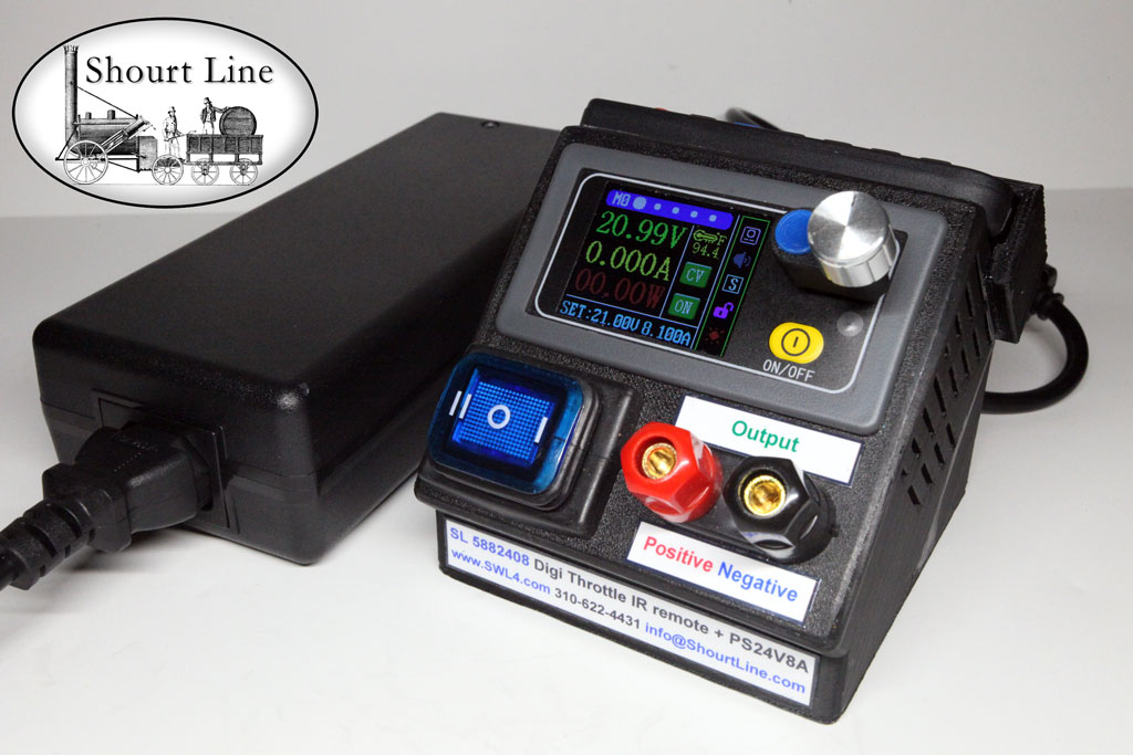
SL-5882408 SL-DC-8-SPS-Set: Any Gauge SL 5882408 400W 50V 8.1A Max. Precision Digi Throttle w IR Remote Control + SL 5112408 Regulated PS 24V 8A AC supply w AC cord
Including
- SL 5882408 8A Amp Digital High Efficiency Precision Voltage/Amperage Throttle
- IR Remote Control Keyboard that stores on the throttle.
- SL 5112408 Regulated Switching Power Supply 24 VDC at 8 Amp with DC output cable for easy plug and play with the throttle
- AC 5 foot power cord
Complete Digital Analog Train Control System
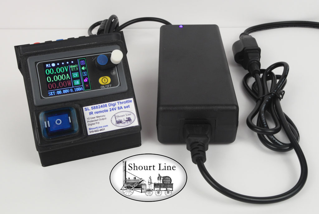
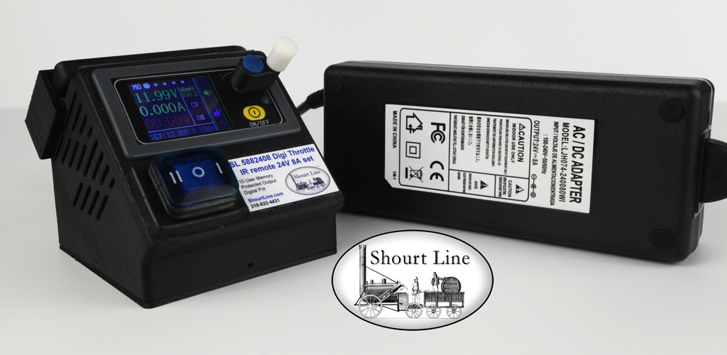
Note that 'M1' memory 1 has been selected for 0 output voltage and 8.1 amps maximum output. Ready for G Scale train operations!
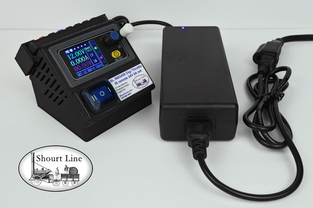
Direct From the Manufacturer - Made in the USA 
Shourt Line Direct Price: $329.95 NEW + Shipping
For international shipping and other payment options contact us by: email info@ShourtLine.com or call 310-622-4431
Features: Get precision control of your analog trains with this ready to run set
For running model trains of any Gauge, the maximum output voltage and amperage as well as wattage can be pre-set in memory and the the throttle is digitally scaled for precise voltage train control. The full color display makes reading voltage, amperage and wattage easy. The Multi-turn scalable pot provides a white 3 ball bearing mounted offset control knob for precision speed control and easy momentum control.
Set Features:
- Simplified User Interface
- 5 Push buttons reduced to just 2
- Easy to Change Menu Screens - use either IR Remote or the Rotary Potentiometer
- Larger Full Color Display
- Large 1.8 inch Full Color Display
- 5 Levels for brightness for indoor and night time use
- Operating Page Display
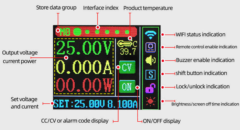
- Readout at the top left of the display shows the current Memory recalled and switched to M0 when user changes either voltage or current
- Readout at the top center of the display shows the current page with a large circle, 8 display pages are available
- Readout of the Input Voltage and Current SET points are always showing at the bottom of the display
- Status Icons are show vertically to the right of the large V, C and W readouts in this order:
- Icon for current internal Temperature and the F or C conversion of display as set by user
- CV or CC Icon (green CV = constant voltage is limiting output, red CC icon = constant current is limiting output)
- Power Icon (shows green ON, red OFF)
- System Icons are show to the right of the Status Icons vertically in the order:
- Icon for WiFi connection status (not visible when no WiFi is connected)
- Yellow beeper Icon shows Yellow ON no icon when beeper is OFF
- Icon for Shift shows Bright Green S when SHIFT is ON, Dark green S when SHIFT is OFF
- Icon for Controls Locked or Unlocked (locked = Icon Locked, unlocked = icon unlocked)
- Icon for Display Always ON & Display timed OFF, Display always ON = Sun Icon, Display Timed OFF = Moon Icon, after a user setting of 1 to 9 min. display = BLACK
- Set Page Display
- Displays all 10 memory settings for easy changing and saving of your choice of Voltage and Current Set points for each memory.
- One of the 10 memory settings can be set to be pre-set on power up and come up with the power ON or OFF as you choose.
- Perfect for displays for unattended operation where the AC power is switch on the last Memory setting is restored and the output is ON, train starts
- Each of the 10 Memory locations provides a user set point when Voltage, Current or Wattage exceeds the limits you set.
- All Memory is nonvolatile so you do not loose your setting when power is off.
- ON/OFF button to turn output ON or OFF
- 2 Control buttons:
- On/Off & Blue Button control all functions in combination with the white knob of the rotary digital potentiometer
- IR Remote Control Keypad:
- IR Remote control with dedicated keys for direct control of all functions.
- Change speed and momentum of your trains with the Remote Control.
- Rotary Digital Pot and Push Button at the center of the pot
- Adjust train speed and momentum using the rotary digital pot
- Adjust Set Point for Voltage, Current or Wattage
- Adjust the Protection voltage, current, wattage and time limits for auto shut down
- Adjust value of Data
- Scale The Multi-Turn Digital Pot variable momentum and precise control of speed, voltage and/or current
- Navigate the menus easily
- Lock all controls on the Throttle via the IR Remote Control Lock and Unlock function key
- 10 User Memory for storing and recalling data values
- Each of the 10 memory location stores:
- Set Points for Voltage, Current or Wattage that load when a memory is selected
- Over Voltage, Current & Wattage Trip Point Protection
- Over Temperature, Watt/Hour & Amp/Hour Trip Point Protection
- Over Time Trip Point Protection
- Auto Load of all Set Points on Power UP
- Output ON or OFF on Power UP
- Nonvolatile Memory Keeps all 10 User memory and System Memory without power
- Electronic Short Circuit, Over Current, Over Voltage and Over Wattage Protection
- High Efficiency
- Automatic Fan Built in for maximum power in hot environments
- Easy Setup
- Easy Operation
- Easy user preference setting of all set points for each memory location, 0 - 9
- Shourt Line Digital analog manual for setup and operation
- USA Designed and manufactured
Options for Shourt Line Digi Precision Throttles:
Order options at the time of purchase
- SL 5880000 For SL-5882408 Only - Wi-Fi for 3rd party Phone and PC Computer Applications
- SL 5800001 For any Digi Throttle - Lab 5 Way Binding Posts for fixed polarity front panel output power
- SL 5800002 For any Digi Throttle - Rear panel USB Output +5V 2.1A for powering USB devices
- SL 5800003 For any Digi Throttle Option for rear panel AUX Power 2.1mm Jack for 2nd throttle or any 24V device
- SL 5800004 For any Digi Throttle Option for rear panel 15Amp Screw Terminal Block for 2nd throttle or any 24V device
Note: The SL 5800003 or SL 5800004 are mounted below the 2.1mm power jack that comes with all Digi throttles and are wired in parallel them. They can be used for either input or output power. Use only 1 power source as input into a digi throttle. Using more that one power source at a time requires special circuitry available upon request.
Digi Throttle Video:
Photos and Features:
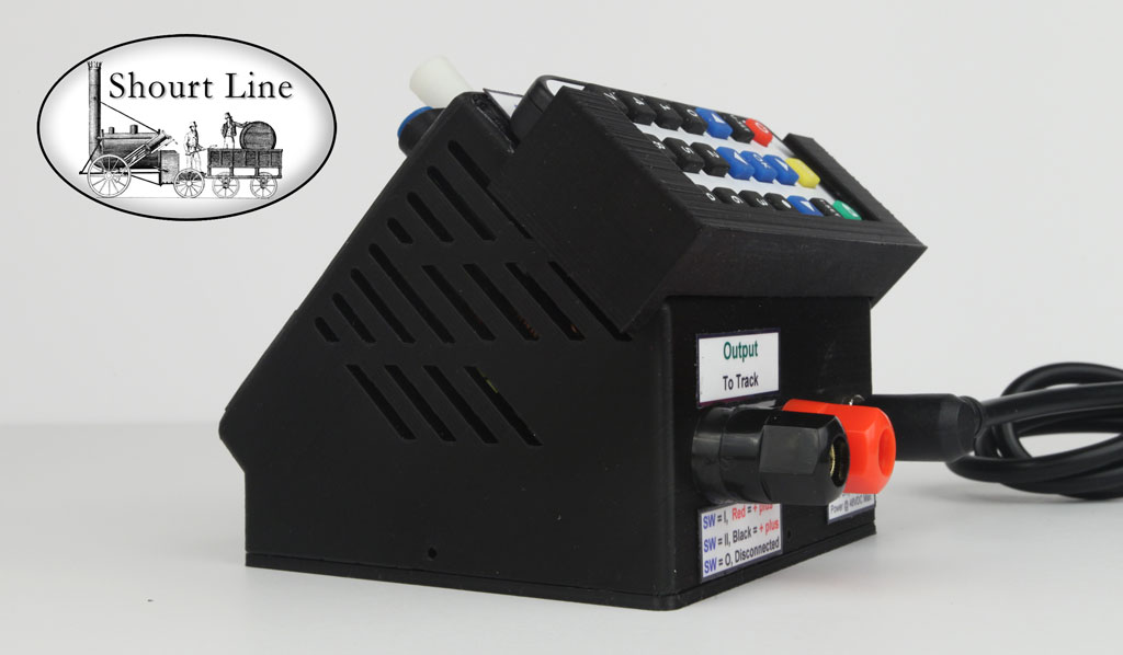
The lighted direction switch on the front panel has three positions; I = Forward, II Reverse, and O = Disconnect from track terminals. The Turn Digital Pot provides precision train operation. (shown above is the SL 5882408 with the optional SL 5800001 Lab 5 Way Binding Posts for fixed polarity front panel output power. The optional SL 5800001 can be used for bench use, testing, battery charging and general lab supply use, the output voltage set by the user in the main screen shows the voltage, current and wattage.
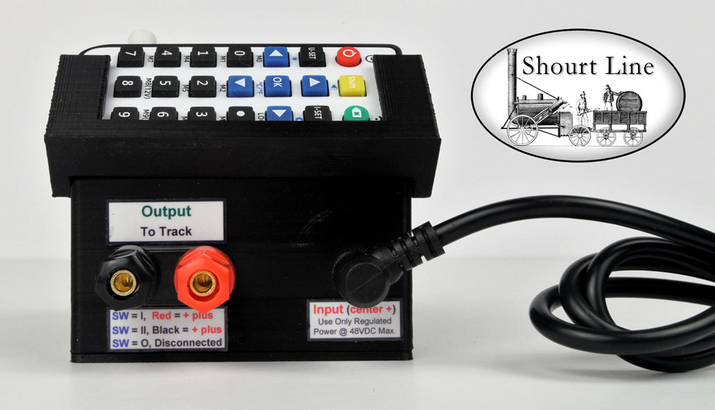
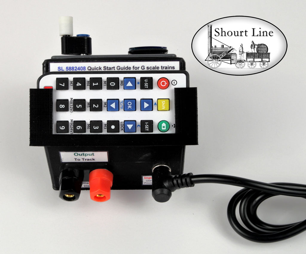
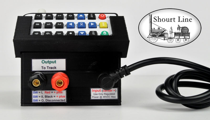
The SL 5882408 comes with track output 5 way binding posts, a 2.1mm power input 10 amp socket, and an IR remote control shown in its holder.
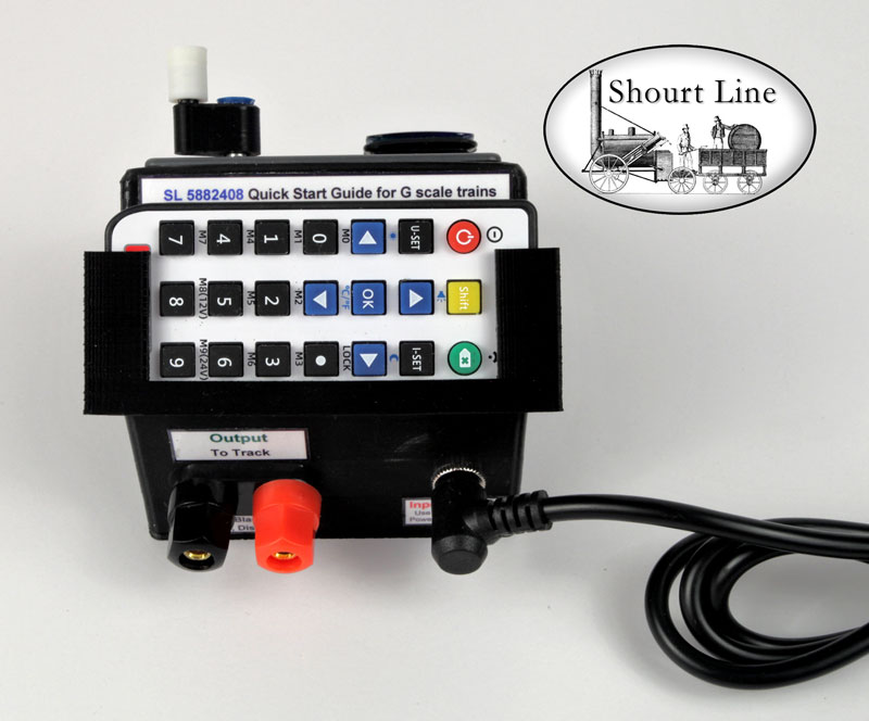
The SL 5882408 comes an IR remote control shown in its holder. It can be removed for handheld operations and slides into the holder for safe storage.
The SL 5882408 can be ordered with the optional SL 5800002 Rear panel USB Output +5V 2.1A for powering USB devices
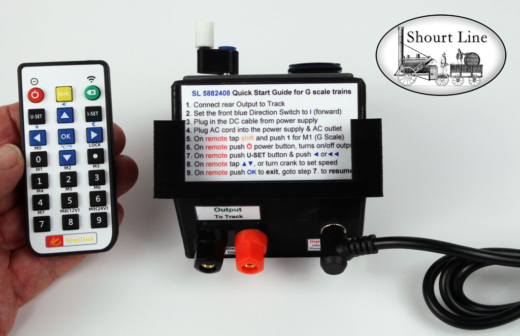
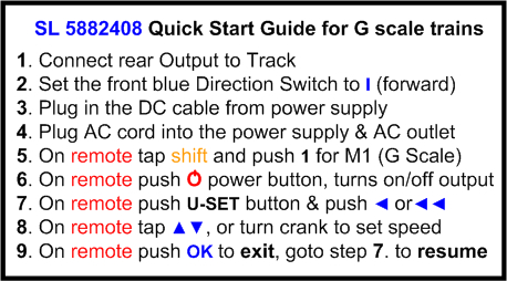
The SL 5882408 IR remote control can be removed from its holder to reveal the SL 5882408 Quick Start Guide for G scale train operation via the M1 Memory setting. Note that the IR Remote Control can be used instead of the blue button, yellow On/Off button, and speed crank digital potentiometer mounted on the front of the throttle.Here is the SL 5882408 Quick Start Guide printed on the top rear of the throttle for operating G scale trains:
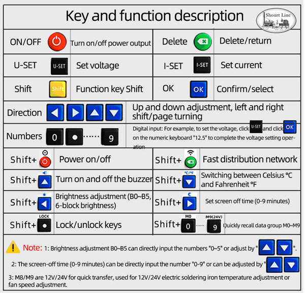
The SL 5882408IR remote control Key descriptions are shown above.
Cooling system:
Louvers on each side provide ventilation for the temperature controlled automatic cooling fan. Note that the interior temperature is displayed on the main screen. The over temperature set point for automatic throttle shut down can be user modified for each of the 10 memory settings.
A electronic over temperature provides fail-safe shut down independent of user setting.
Memory Settings:
The following memory settings have been setup for you and can be changed by you at any time in the throttle memory. Are the memory settings are saved when the power is turned off and come back when power is turned on.
Memory location 0 is always shows the last user selected voltage/current
M0 default Set Point set by user selected voltage and/or currentThe following memory locations can all be changed by user and pre-programmed for you:
M1 voltage output = 0 current output = 8.1 amps max (G Scale operation)
M2 voltage output = 2.1 current max. = 10 ma for testing color LEDs
M3 voltage output = 3.1, current max. = 15 ma for testing white or blue LEDs
M4 user defined
M5 voltage output = 5.0, current max. = 8.1 amps
M6 user defined
M7 user defined
M8 voltage output = 12.0, current max. = 8.1 amps
M9 voltage output = 24.0, current max. = 8.1 ampsThe system configurations, like screen brightness, sound on/off, etc. are also saved on power off and restored on power on. The are explained in detail below.
Highlights:
- Up to 8 Amps track current at any maximum track voltage for any Scale Railroad
- Run Trains of ANY Gauge with user selection of maximum voltage, current & wattage in each of 10 memory settings
- Memory #1 preset for G scale train operation
- IR Remote Handheld Keypad Controller
- Automatic short circuit protection
- 1.8 Inch Color LCD Screen
- Speed Crank Digi Potentiometer with scalable output for momentum control and precision control
- Push button electronic ON/OFF of output power
- 3 Position Track Switch for Forward (I), Reverse (II) and total track isolation (O)
- Special High Temp ABS housing designed for maximum convection cooling
- 5 Way Gold Plated terminal binding posts with banana sockets on the back for connecting bare track wires, dual banana plug or spade lugs
- 2.1mm 10 Amp Power Input Jack for fast input power connection of the 24V 8A switching power supply.
- Speed Crank Digital Pot with user selected 1, 6 or 60 turn rotary ball bearing knob on an offset shaft for fast or slow loco acceleration-braking.
- 10 user Memory settings for voltage and amperage
- Nonvolatile memory for storing all 10 sets of user preferences when power is off
Specifications:
- Input voltage range 6-52VDC (regulated voltage)
- Output voltage range: 0-50VDC
- Output current voltage range: 0-8.1 Amps
- Output power range: 0-400W
- Output voltage resolution: 0.01V
- Output current resolution: 0.001A
- Output Voltage accuracy 1% (1 digit)
- Output Current accuracy 1% (2 digits)
- Automatic Fan for cooling
- 10 user memory
- Protection trigger point memory for over; voltage, current, wattage & time (set by user)
- Nonvolatile Memory - stores all setting when power is off
- Case made from high temp ABS
- Input power plug rated 10 amps at 24 volts DC
- Fwd/Off/Rev/Disconnect LED lighted Switch rated at 16 amps
Overview of how to use the Display Screens and Functions:
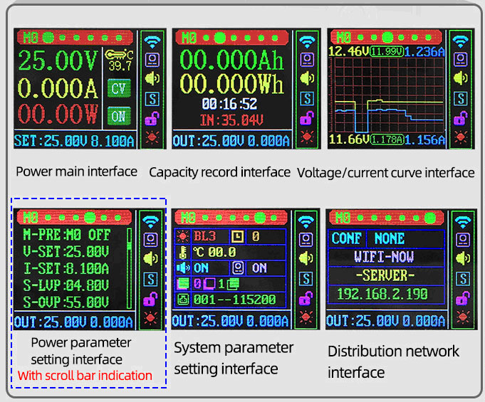
Overview of the 6 display screens:
- The Main Screen (top left below) is shown on power up.
- Turning the speed crank changes the display screens in the order shown below.
- All functions can be done from either the IR Remote control or the 2 buttons on the throttle and by turning the white knob on the digital pot.
- You can also use the IR Remote in combination with the 2 buttons and white knob on the digital pot.
- If you can not move between screens above push the blue button on the digital pot for 2 seconds or push OK button on the IR Remote
- Note the Interface index at the top of the screen changes with each display screen.
Main Interface Screen:
This screen is shown on power up. It is used to set voltage (train speed) and current..
For running trains push the U-Set button on the IR Remote to 'lock' the throttle into speed setting mode, push OK to 'unlock'
Follow this guide that is printed on the top back of the throttle for a quick train startup.
Use the IR Remote to easily change these settings
- Push either the U-SET button (to lock speed setting mode) for voltage setting or train speed control OR push the I-SET Button for current setting.
- Push the ◄► buttons to select a variable digit to be changed (for train control select the 1/10 volt digit for medium momentum)
- After selecting, your selection is displayed in reverse blue, the value or speed can be changed via the ▲▼ buttons (or speed crank)
- Push the blue OK button to Exit setting mode
Use the Throttle buttons and white digital pot crank to change settings (Note: after 6 seconds without changes the display will Save & Exit settings mode
- Tap (short press) the blue button on the center of the digital pot code pot to Enter setting mode
- Rotate the white digital pot crank to select a parameter to be set. After selecting, the parameter will be is displayed in reverse blue
- Tap the blue button to select, as desired, a variable or digit to be changed
- Rotate the white digital pot crank to change the selected item.
- Push the blue OK button for 2 seconds to Save & Exit setting mode or wait 6 seconds and the system will automatically Save & Exit setting mode
OR use Both the IR Remote and the Throttle controls at the same time. This is deal for running trains where you want to continuously change train speeds by adjusting the speed crank or pushing the IR Remote ▲▼ buttons. See quick start guide above for train operation.
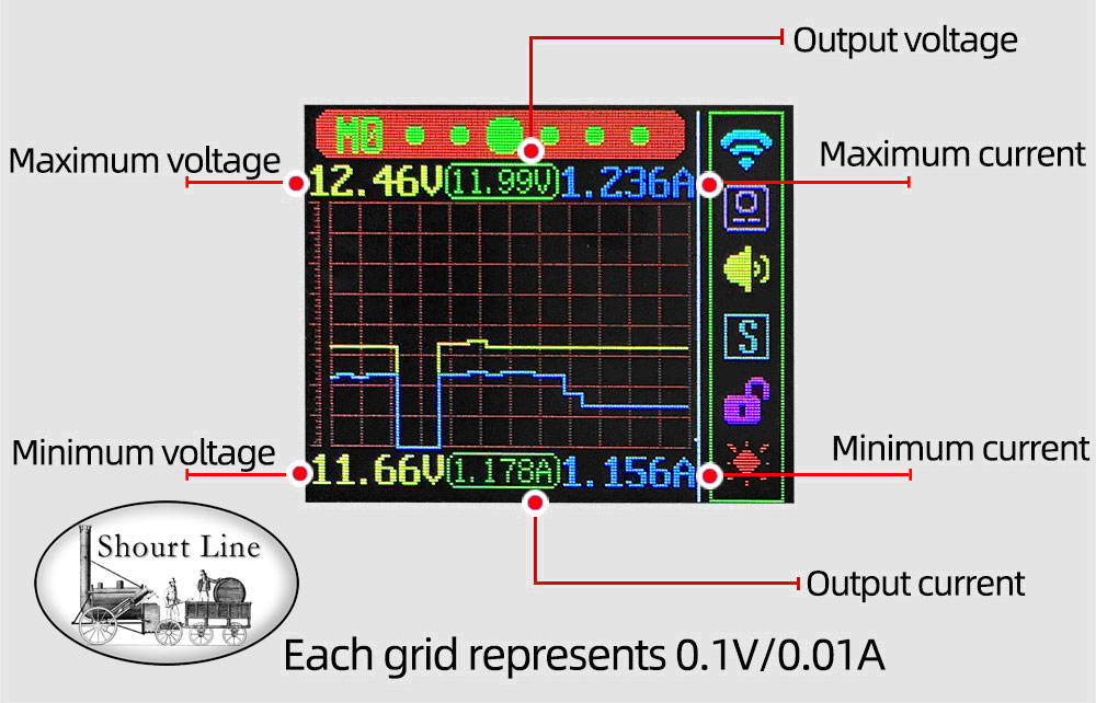
Moving Voltage and Current Display Screen (#3):
Short press the green button on the center of the digital potentiometer speed crank to pause/start curve writing. The voltage and current display over time is perfect for trouble shooting layout track power problems, locos issues like motor and gear train health, or intermittent shorts due to locos shorting track current due to track or locomotive issues
The moving display graph is is also useful for displaying current loading of train and locomotive buffers quickly suck up current when track power is turned on. You can easily see the spike and duration of current over time and it’s effect on actual track voltage.
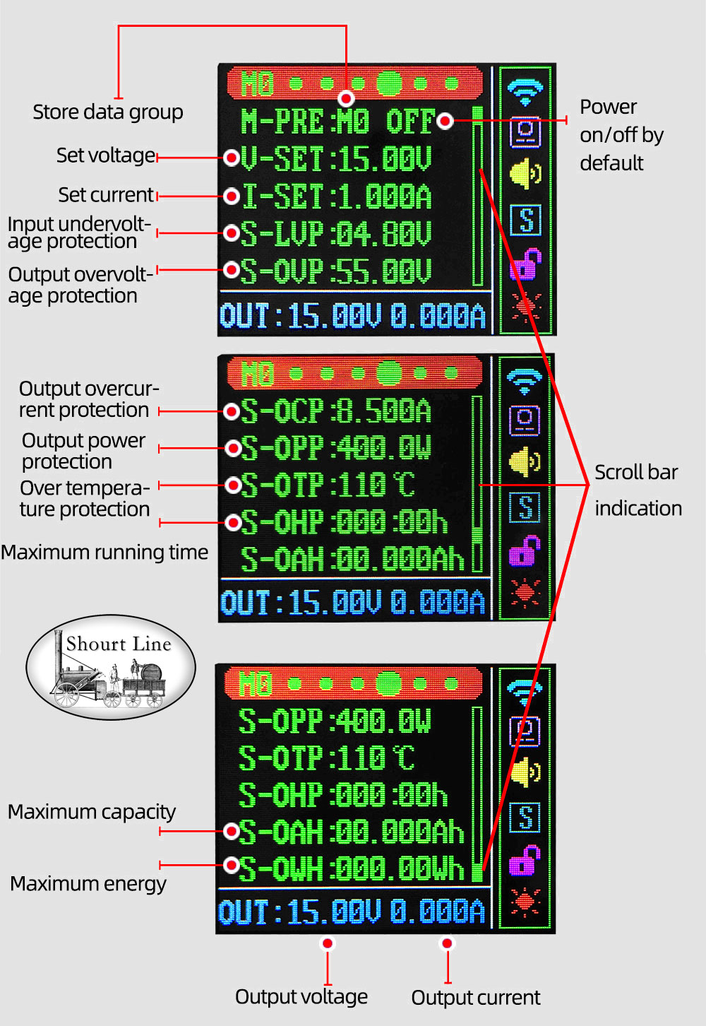
Memory Parameter Setting Interface Screen (#4):
- This screen is used to review and change your preference for the 10 memory settings.
- Remember M1 is reset for running G Scale Trains with up to 8.1 amps of output current.
Note the vertical scroll bar at the right side of the variable display that shows where you are in the list
Use the IR Remote to easily change these settings
- Push the blue OK button to enter setting mode.
- Push the ◄► buttons to select a variable to be changed
- After selecting, your selection is displayed in reverse blue, and the value can be changed via the ▲▼ buttons
- Push the blue OK button to exit setting mode
Use the Throttle buttons and white digital pot crank to change settings (Note: after 6 seconds without changes the display will Save & Exit settings mode
- Tap (short press) the blue button on the center of the digital pot code pot to Enter setting mode
- Rotate the white digital pot crank to select a parameter to be set. After selecting, the parameter will be is displayed in reverse blue
- Tap the blue button to select, as desired, a variable or digit to be changed
- Rotate the white digital pot crank to change the selected item.
- Push the blue OK button for 2 seconds to Save & Exit setting mode or wait 6 seconds and the system will automatically Save & Exit setting mode
OR use Both the IR Remote and the Throttle controls at the same time.
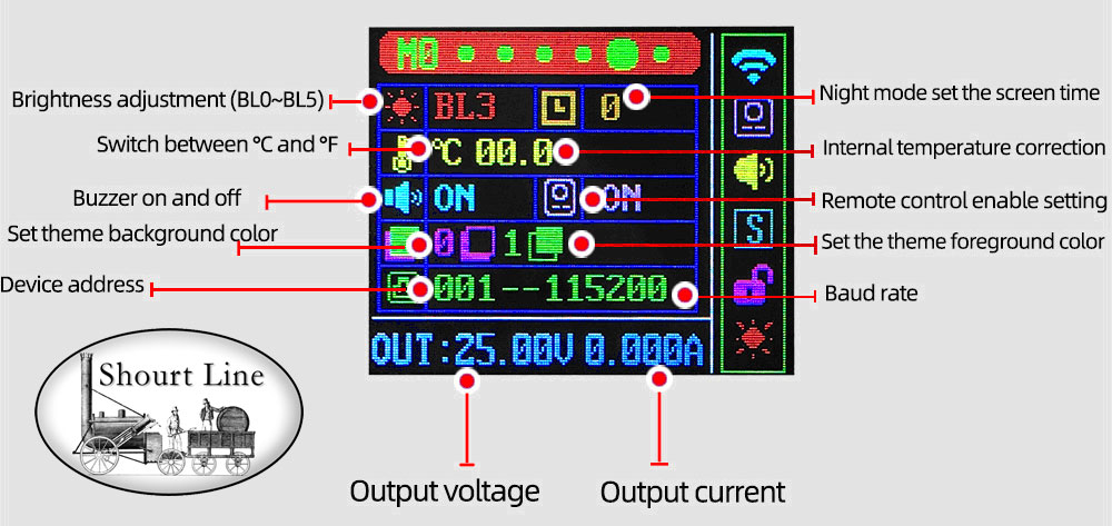
System Memory Setting Display Screen (#5:
- These settings are stored in nonvolatile memory.
Use the IR Remote to easily change these settings
- Push the blue OK button to enter setting mode.
- Push the ◄► buttons to select a variable to be changed
- After selecting, your selection is displayed in reverse blue, and the value can be changed via the ▲▼ buttons
- Push the blue OK button to exit setting mode
Use the Throttle buttons and white digital pot crank to change settings (Note: after 6 seconds without changes the display will Save & Exit settings mode
- Tap (short press) the blue button on the center of the digital pot code pot to Enter setting mode
- Tap the blue button as many times as need to select the variable to be changed, the parameter will be is displayed in reverse blue
- Rotate the white digital pot crank to make changes. After changing, the parameter will be is displayed in reverse blue
- Repeat 2nd step above for more changes OR
- Push the blue OK button for 2 seconds to Save & Exit setting mode OR wait 6 seconds and the system will automatically Save & Exit setting mode
OR use Both the IR Remote and the Throttle controls at the same time.
AC Power Supply :
Shourt Line SL 5112408 Enclosed SL 8 Amp 24V Power Supply
Easy to use enclosed full feature regulated switching power supply with regulated pure DC power a superior power source for SL 8 Amp Digital Pot Throttles
Features:
- High efficiency
- High reliability
- Silent Operation
- Protections:
- Over-voltage
- Over-current
- Over-power
- Over-temperature
- Short-circuit
- VAC auto input 100 - 230VAC 50/60Hz
- 100% full load burn-in test
- Cooling - convection
- LED Power on indication
- AC Power IEC socket output on Power Supply
- IEC plug molded connector to AC molded 2 prong plug with ~5 foot cable
How to hookup and use the SL Digi Throttle Sets:
Get precision control of your analog trains with this ready to run set
Follow the Quick Setup Guide printed on the rear top of the 8 amp throttle:
Use these instructions for setup on any digi throttle set:
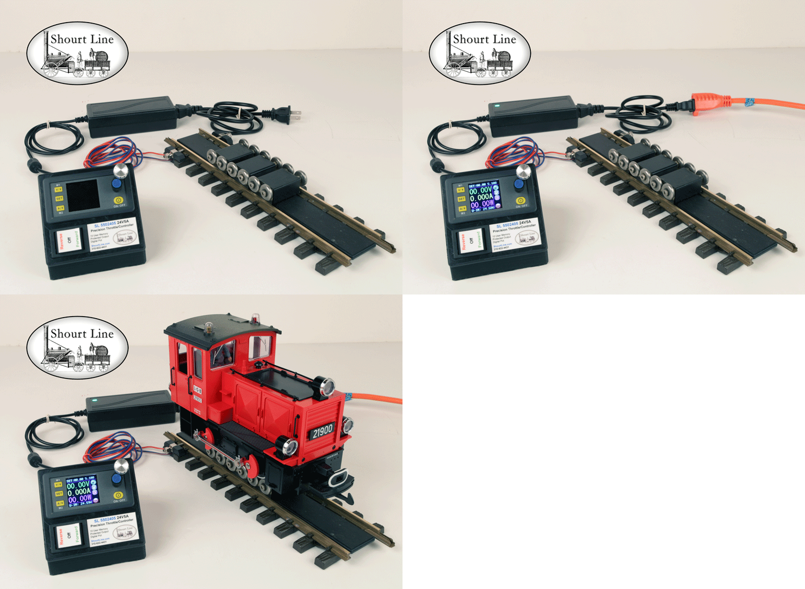
1) Plug the power supply output cable to the throttle's input jack
2) Connect track wires to the throttle's output 5 way binding posts.
3) Connect AC Power: The SL Digital Throttle comes preset for running G Scale Trains using memory setting M1. See instructions or tutorial for setting up other memory locations for different Gauge Trains with your choice of maximum voltage, current or wattage allowed.
(Piko quick connect power track clips show above are optional) The binding posts work with up to 12AWG size cable. Choose cable size depending on your cable length;: use 18AWG cable for up to 10 feet, use 16 AWG for 10 to 30 feet and 14AWG cable up to 100 feet and over 100 feet use 12AWG cable (all available at our store) The larger the cable the lower the power loss.4) Push the Power ON/OFF button to connect the output power and the Forward or I button to set the direction and you are ready to run.
5) With the 8 amp you can use the IR remote control (see quick start guide above) or run from the throttle by tapping the blue button 3 times for medium momentum, with the 5 amp throttle push the V button and tap the blue button 2 times, then rotate the speed knob clockwise for faster speeds, counter clockwise for slower speeds and stop.
HINT: Use the IR remote when you want to 'lock' the throttle in train speed control. Once it is 'locked', you can use either the crank or the up/down blue buttons to change speed. To 'unlock' and Exit the speed mode do one of the following: Push the OK button on the IR Controller or push the blue button on the digi pot for 2 seconds. See the Quick Start Guide below and printed on the top of the 8 amp throttles.
To change the momentum and accuracy of track voltage push the blue button at the center of the rotary control to cycle through your choice of 1V, 1/10V and 1/100V steps. With the 8 amp throttle you can use the IR remote to change both the speed and the number of speed steps (see step 7 and 8 of the Quick Start Guide above)
/
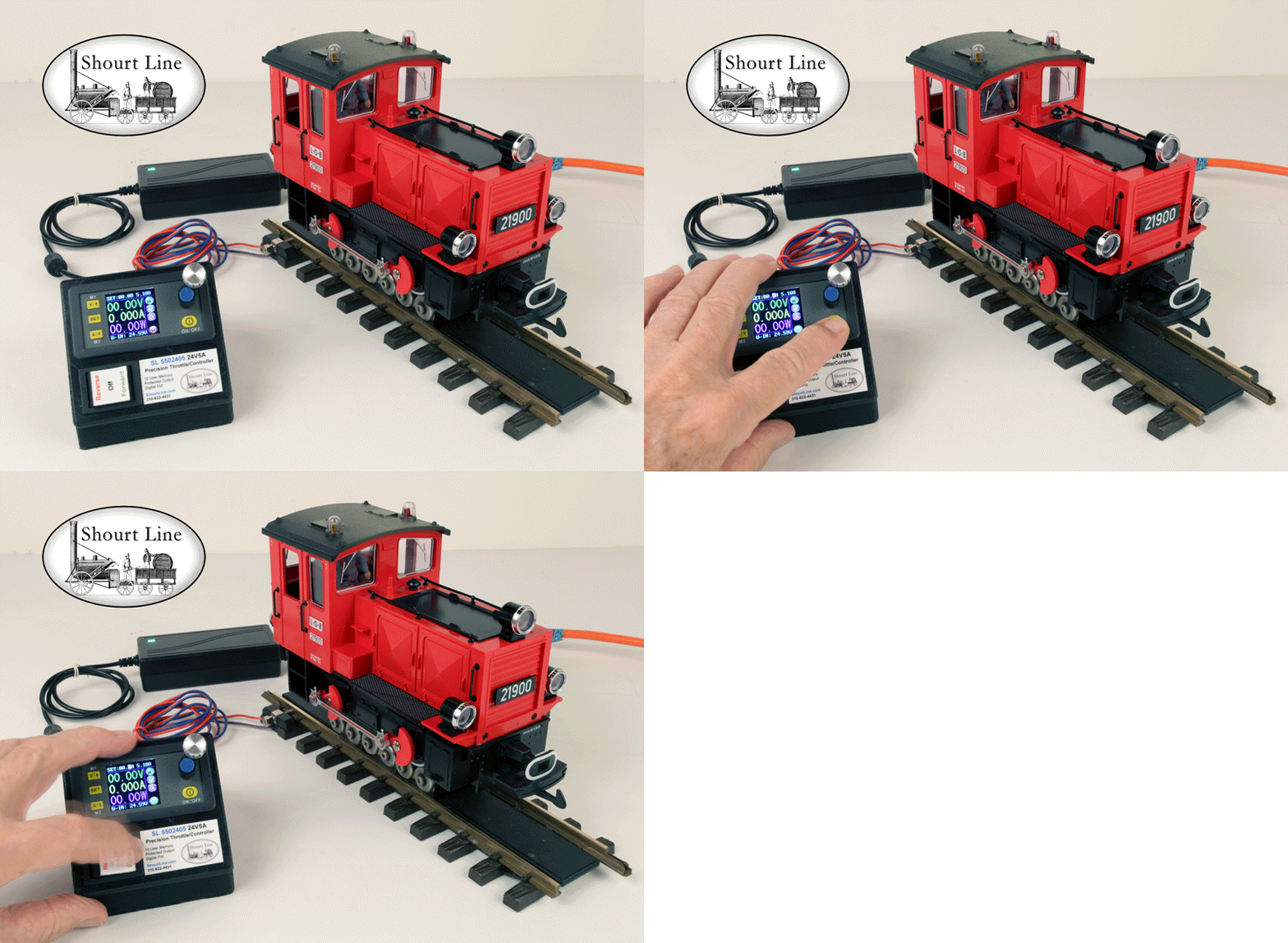
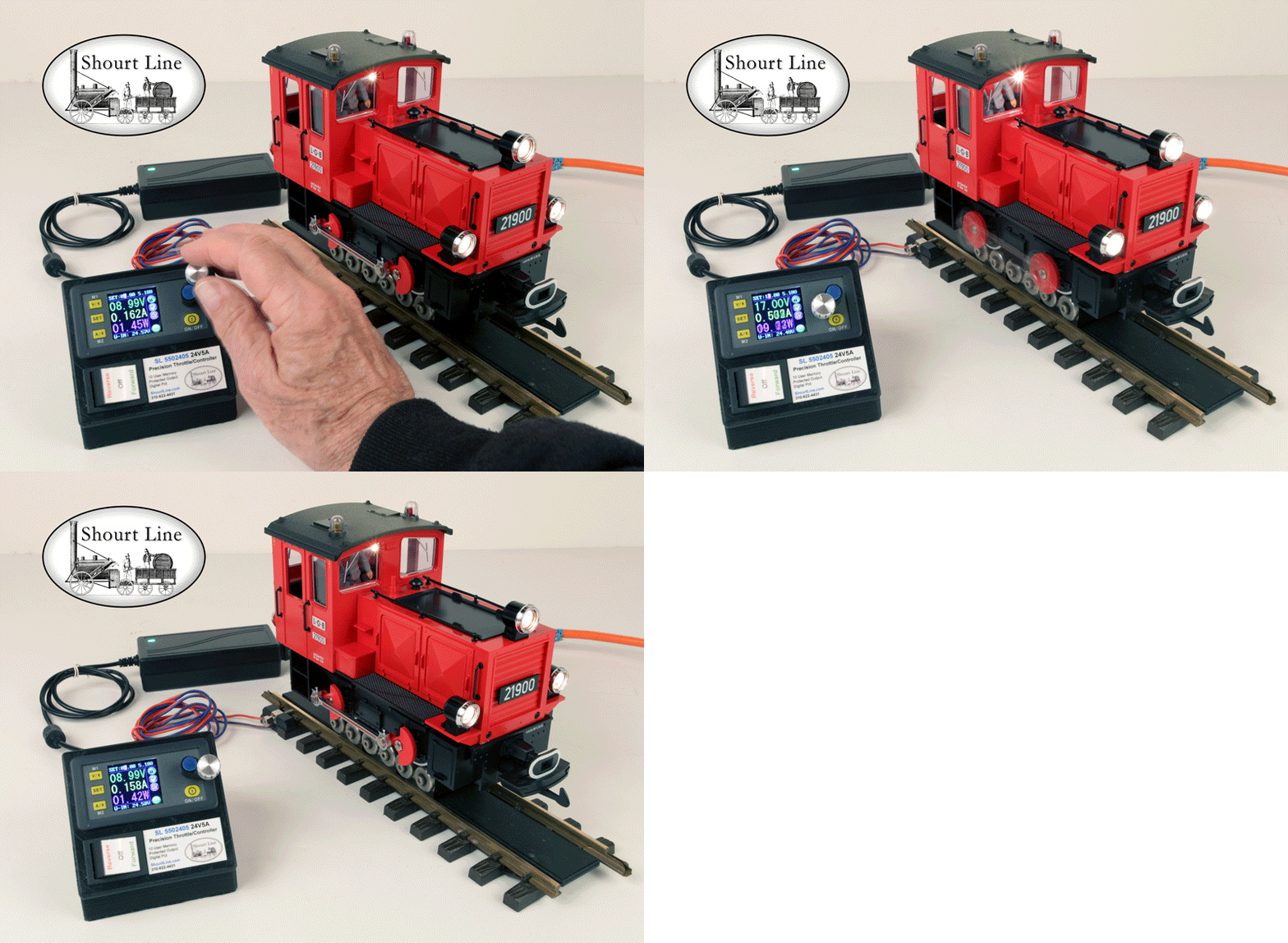
Run any Gauge Analog Layout! (loco, track and track power clips not included)The Shourt Line digi precision throttle sets come in 2 power sizes:
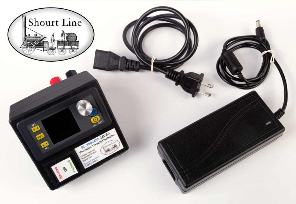
The 5 amp (above) and 8 amp (below) models are available direct from the manufacturer. Made in the USA - Shourt Line by Soft Works Ltd.
For questions email info@ShourtLine.com or call 310-622-4431
Thanks for looking - Shourt Line by Soft Works Ltd.
copyright 2024 ShourtLine.com - Soft Works Ltd. all rights reserved
